
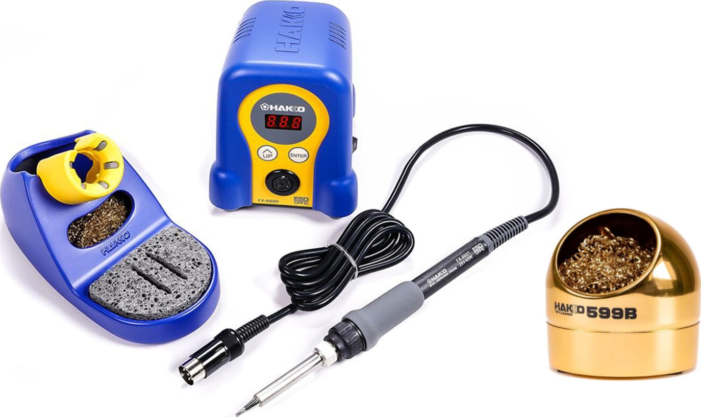
Hakko FX888D-23BY Digital Soldering Station
All soldering steps; adjustable 120-899°F for fine DC wires.
$99.99
Hakko FX888D-23BY Digital Soldering Station Precise temperature control essential for reliable joints without overheating components.
Get the App
Better experience on mobile
Build safe, reliable custom AC adapters for DIY electronics projects with expert step-by-step wiring instructions tailored for advanced users.
Custom AC adapters are essential for powering vintage gadgets, custom Arduino projects, or repairing devices where stock adapters fail. Off-the-shelf options often don't match exact voltage, polarity, or connector needs, leading to frustration or damage. Wiring your own gives precise control, saves money, and teaches valuable electronics skills.
This guide walks you through safely assembling a custom AC-DC adapter using a universal AC input cord, DC output jack, and enclosure. You'll handle high-voltage AC input (120V) and low-voltage DC output safely. Expect to complete a fully functional adapter tested for continuity and polarity.
The process involves component selection, soldering, insulation, and testing. It's advanced due to soldering and electrical safety—requires prior experience with tools like multimeters. Total time: 1-2 hours, plus cooling periods. Work in a well-ventilated area; always unplug from mains during assembly.
Estimated Time: 1-2 hours Difficulty: advanced
Before wiring, confirm your device's requirements: voltage (e.g., 12V DC), current (e.g., 2A), polarity (center positive/negative), and connector size (e.g., 5.5x2.1mm). Use a multimeter on the original adapter if available.
Match components: AC cord must handle input voltage (120V AC US), DC jack polarity (typically center +). Why? Mismatch fries circuits. Success: Specs noted on paper; parts rated equal/higher than needs.
Image Description: Close-up of multimeter probing original adapter barrel jack, showing voltage/polarity readout.
💡 Tips:
⚠️ Warnings:
Unplug all tools; work on non-conductive surface. Wear gloves/glasses. Ventilate for solder fumes. Secure enclosure with clamps.
Why safety first? AC side is lethal (120V). Expect a clean, organized bench. Success: No loose wires, tools powered off.
Image Description: Organized workbench with tools laid out, safety gear visible.
💡 Tips:
⚠️ Warnings:
Cut AC cord to 6 inches from plug end. Strip outer jacket 1 inch, inner wires 1/4 inch. Identify live/neutral (ribbed/smooth insulation) and ground (green).
Tin wires with solder for strength. Why? Prevents fraying in enclosure. Success: Clean, tinned leads without nicks.
Image Description: AC cord stripped, wires tinned with solder.
💡 Tips:
⚠️ Warnings:
Cut DC wire lengths: 4 inches red (+), 4 inches black (-). Strip 1/4 inch ends, tin them. Solder red to DC jack center pin (positive), black to outer sleeve (negative).
Confirm polarity with multimeter (continuity test). Why precise? Wrong polarity damages devices. Success: Secure solder joints, shiny and volcano-free.
Image Description: Soldering iron joining red wire to DC jack center pin.
💡 Tips:
⚠️ Warnings:
Drill holes for DC jack (per template) and AC cord strain relief. Mount jack with nut. Feed AC cord through grommet, secure with zip tie.
Route wires neatly. Why? Prevents shorts/vibration failure. Success: Snug fit, no exposed metal.
Image Description: Enclosure with drilled holes, DC jack mounted.
💡 Tips:
⚠️ Warnings:
If using a pre-built AC-DC module (e.g., HLK-PM01), solder AC live/neutral to module input, DC wires to output. Skip if direct wiring.
Insulate all joints with heat shrink. Why? Module handles conversion safely. Success: Wires matched by color/code.
Image Description: AC-DC converter module wired inside enclosure.
💡 Tips:
⚠️ Warnings:
Slide heat shrink over joints pre-soldering, shrink with heat gun. Add electrical tape over exposed terminals. Bundle wires with zip ties.
Why? Prevents arcing/shorts. Success: No bare wire visible.
Image Description: Heat shrink tubing applied and shrunk on solder joints.
💡 Tips:
⚠️ Warnings:
Set multimeter to continuity/ohms. Check DC output: no shorts (+ to -). Verify polarity.
Why? Catches errors pre-power. Success: Beeps only on correct paths, 0 ohms polarity.
Image Description: Multimeter leads on DC jack testing continuity.
💡 Tips:
⚠️ Warnings:
Plug into GFCI outlet. Use multimeter DCV mode on output with dummy load (e.g., 12V bulb). Monitor for heat/smoke.
Success: Stable voltage, no issues after 10 mins.
Image Description: Custom adapter plugged in, multimeter showing output voltage.
💡 Tips:
⚠️ Warnings:
Problem: No output voltage
Solution: Check continuity on all joints; verify module input AC live/neutral swapped? Retest polarity.
Problem: Adapter gets hot
Solution: Undersized components or short; unplug, inspect insulation, add heatsink to module.
Problem: Intermittent power
Solution: Loose solder—reflow joints; secure wires better.
Problem: Sparking on plug-in
Solution: Short circuit; disassemble, check for bare wires touching. Seek pro if unsure.
Precise temperature control essential for reliable joints without overheating components.
Best for: All soldering steps; adjustable 120-899°F for fine DC wires.
Price Range: $99.99
Accurate AC/DC voltage, continuity, and polarity testing critical for safety.
Best for: Spec verification, testing every step; auto-ranging for ease.
Price Range: $29.99
Assorted sizes for perfect fit on all joints, professional insulation.
Best for: Insulating soldered connections; waterproof and durable.
Price Range: $15.99
Reliable 5.5x2.1mm jacks match most devices; solderable for customs.
Best for: DC output connector; bulk pack for multiple projects.
Price Range: $9.99
Flexible, high-temp wire perfect for DC side in tight enclosures.
Best for: Internal wiring; red/black colors for polarity ID.
Price Range: $12.99
All soldering steps; adjustable 120-899°F for fine DC wires.
Hakko FX888D-23BY Digital Soldering Station Precise temperature control essential for reliable joints without overheating components.
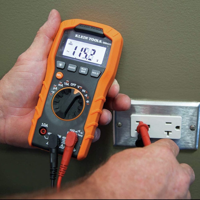
Spec verification, testing every step; auto-ranging for ease.
Klein Tools MM400 Digital Multimeter Accurate AC/DC voltage, continuity, and polarity testing critical for safety.
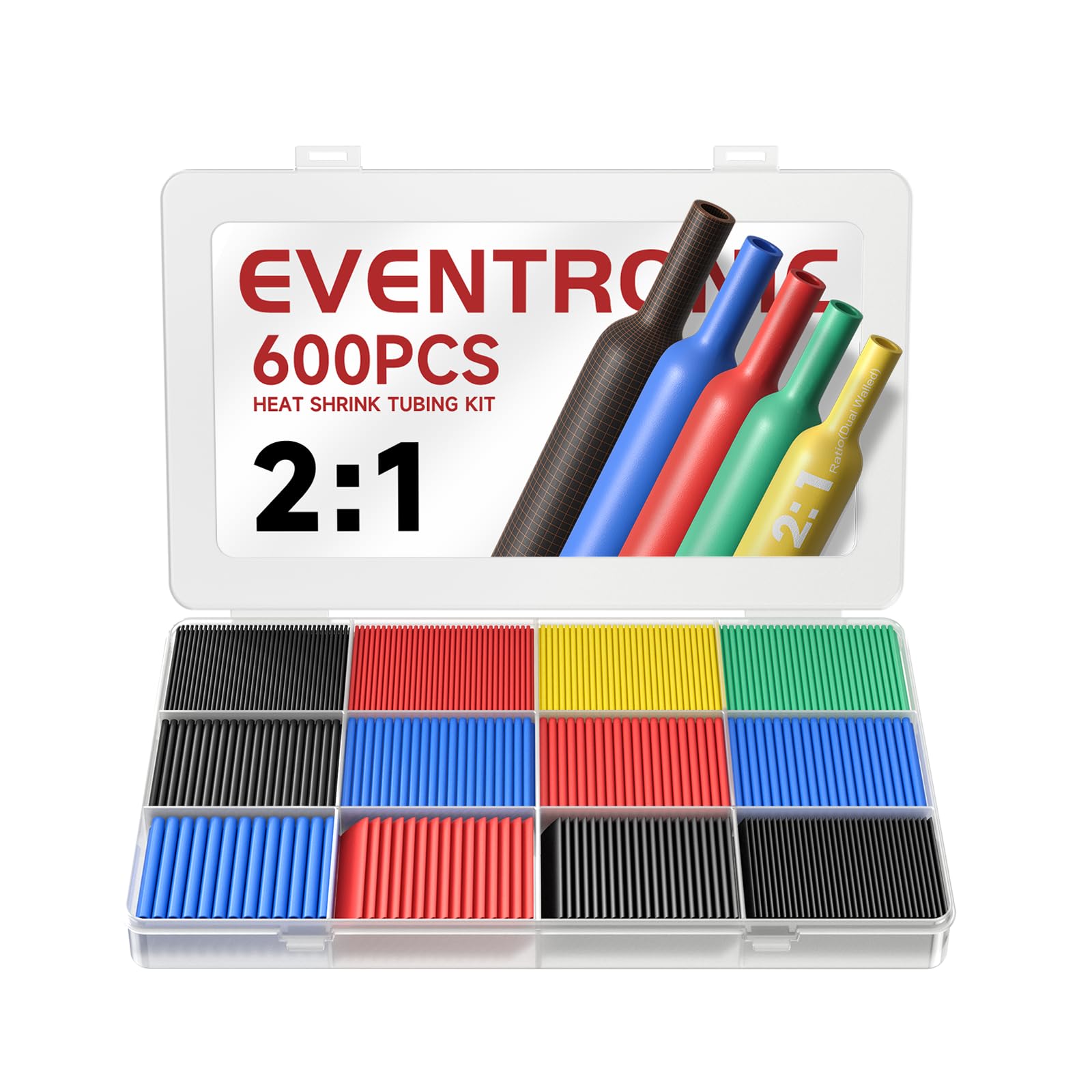
Insulating soldered connections; waterproof and durable.
Eventronic Heat Shrink Tubing Kit 650pcs Assorted sizes for perfect fit on all joints, professional insulation.
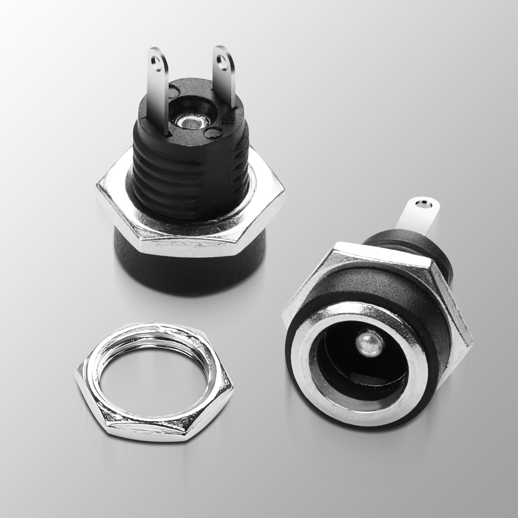
DC output connector; bulk pack for multiple projects.
GME 10 Pack DC Power Jack Female Panel Mount Reliable 5.5x2.1mm jacks match most devices; solderable for customs.
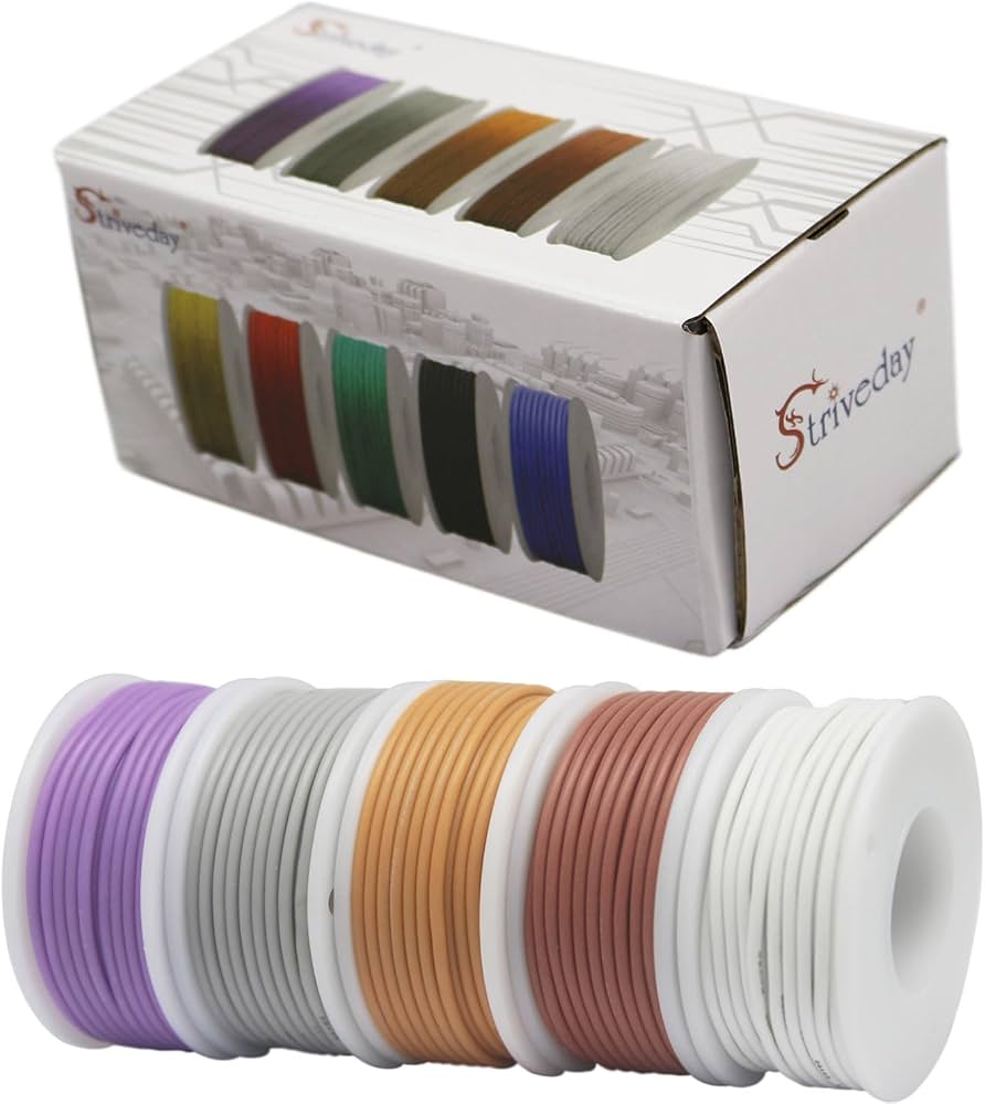
Internal wiring; red/black colors for polarity ID.
Hilitchi 24 AWG Silicone Wire Kit Flexible, high-temp wire perfect for DC side in tight enclosures.