In a world of portable tech, standard power banks often fall short in size, capacity, or customization. Whether you're powering Arduino projects, drones, or emergency phone chargers, wiring your own 5V battery pack delivers compact, high-capacity power tailored to your needs. This guide tackles the common pain point of unreliable DIY power by teaching safe, professional-grade assembly.
You'll learn to integrate 18650 Li-ion cells with charging and boost modules for stable 5V USB output. Expect to cover safety protocols, soldering techniques, testing, and enclosure—everything for a pro-level build. As an advanced tutorial, it assumes soldering proficiency and electronics basics; total time is 1-2 hours.
By the end, you'll have a functional 5V USB battery pack that outperforms off-the-shelf options, with capacity up to 10Wh+ per cell.
▸What You'll Need
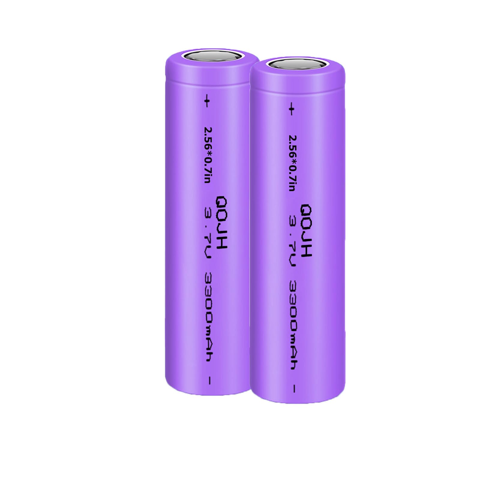
- •1-2x 18650 Li-ion batteries (e.g., Samsung 30Q, 3000mAh+)
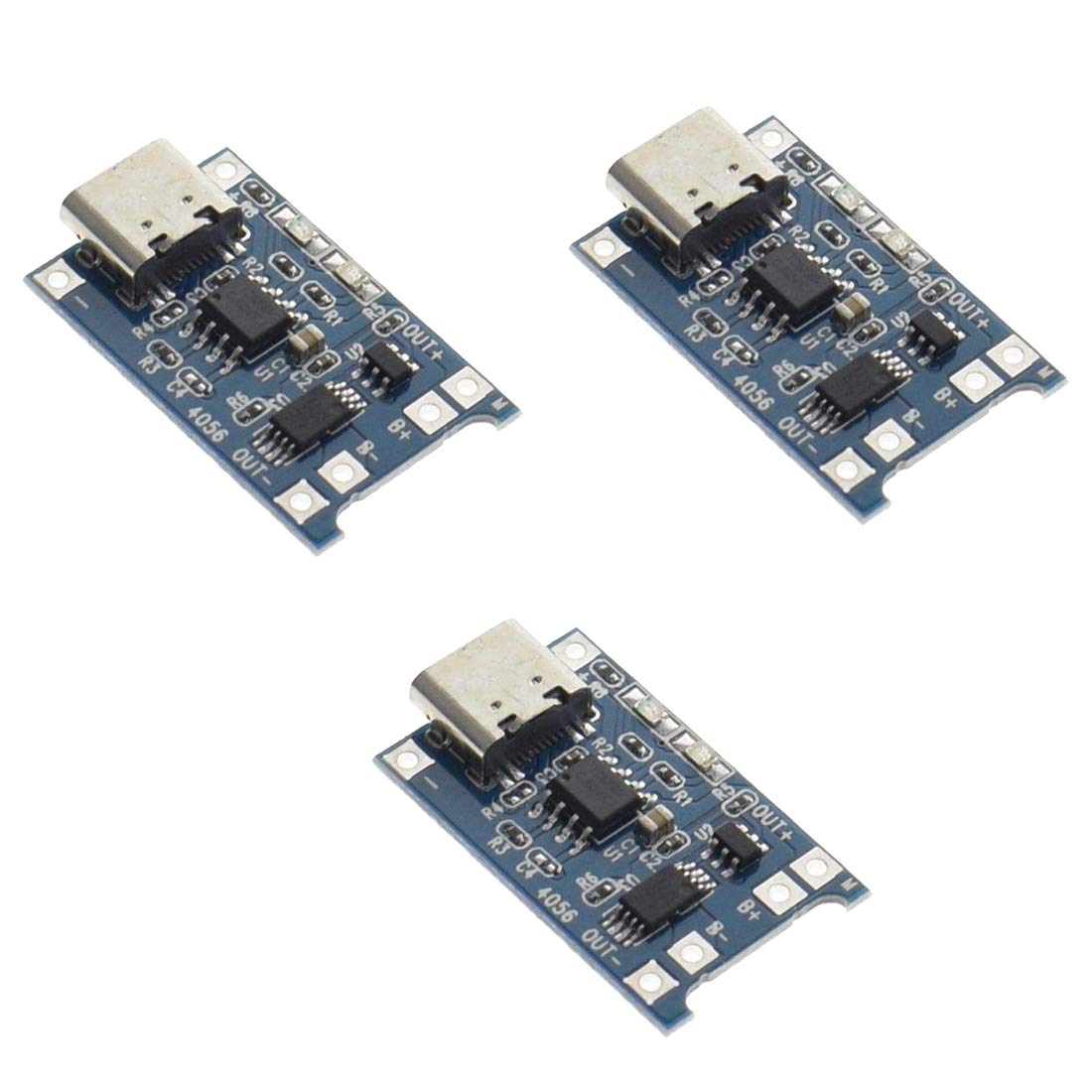
- •TP4056 lithium battery charger module (with protection)
- •MT3608 DC-DC boost converter module
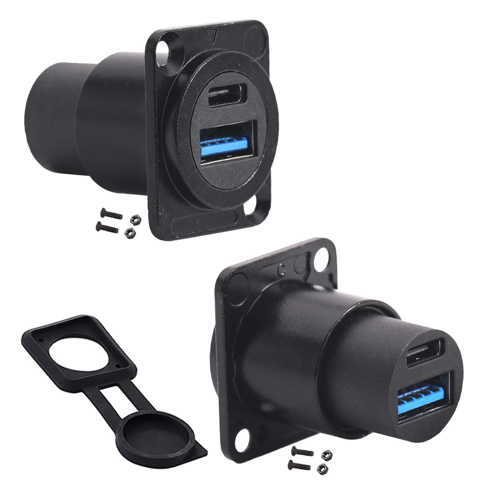
- •USB Type-A female breakout board or panel mount connector
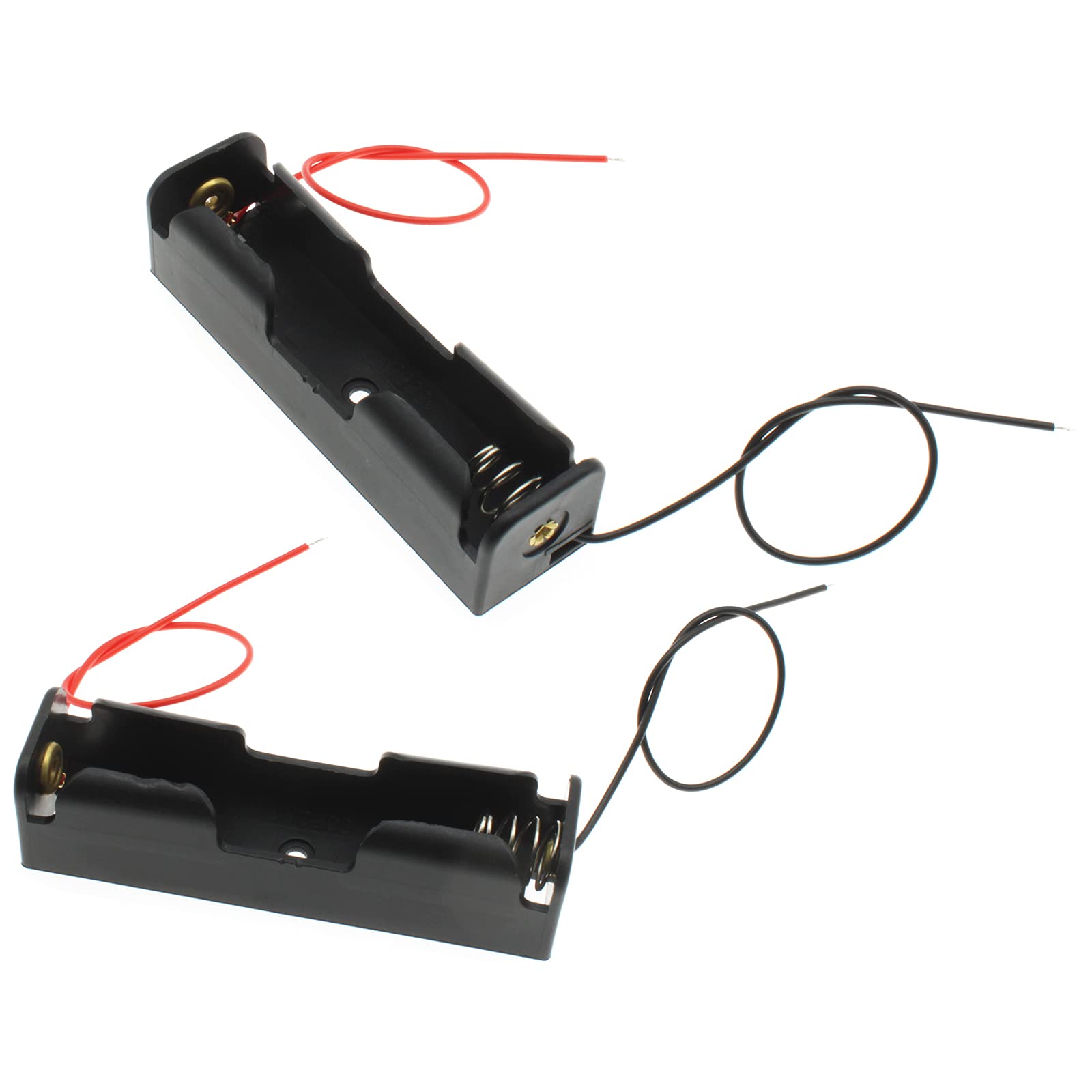
- •18650 battery holder (single or dual cell)
- •22-24 AWG silicone wire (red/black, 10-20cm lengths)
- •Soldering iron (30-60W with fine tip), solder, flux
- •Multimeter for voltage/current testing
- •Heat shrink tubing (assorted sizes), wire strippers, helping hands
- •Optional: Toggle switch, 3D-printed or plastic enclosure, hot glue gun
Estimated Time: 1-2 hours
Difficulty: advanced
▸Step-by-Step Instructions
Step 1: Inspect and Prepare Components
Unpack all parts and visually inspect for damage—check battery wrappers for dents/swells, modules for bent pins. Discharge batteries if previously used by connecting a load until <3V (measure with multimeter). Clean module pins with isopropyl alcohol.
Why it matters: Faulty components cause fires or failures. Success: All parts verified functional; batteries at safe voltage (3.0-4.2V).
Label wires: red for positive (+), black for negative (-). Cut wires to length.
💡 Tips:
- •Use protected 18650 cells with built-in PCB for extra safety.
- •Test batteries individually with multimeter in voltage mode.
⚠️ Warnings:
- •Never short-circuit Li-ion cells—risk of fire/explosion.
Step 2: Mount Battery in Holder
Snap the 18650 battery into the holder, ensuring polarity matches (usually + on top). Solder short red wire to battery + terminal and black to -. Insulate exposed terminals with heat shrink.
Why: Creates a stable mechanical connection for wiring. Expect: Secure, wiggle-free battery pack.
For dual cells, wire in parallel (+ to +, - to -) for doubled capacity.
💡 Tips:
- •Parallel config boosts mAh without voltage change.
- •Add thermal pad under battery for heat dissipation.
⚠️ Warnings:
- •Confirm polarity with multimeter before powering on.
Step 3: Wire Battery to TP4056 Charger
Solder battery pack's red wire to TP4056 B+ pad, black to B-. The TP4056 handles charging/discharging protection via Micro USB input.
Why it matters: Protects against overcharge/over-discharge. Success: Continuity test shows <1Ω resistance between B+/B- and battery.
Apply flux for clean joints; heat shrink solder points.
💡 Tips:
- •Tin wires and pads first for quick soldering.
- •TP4056 LEDs: Red=charging, Blue=full.
⚠️ Warnings:
- •Reverse polarity fries the module instantly.
Step 4: Configure MT3608 Boost Converter
Connect TP4056 OUT+ to MT3608 VIN+, OUT- to VIN-. Use potentiometer on MT3608 (turn clockwise/counter to adjust) to set output to exactly 5.0-5.2V (measure no-load with multimeter on VOUT pins).
Why: Boosts 3.7V battery to stable 5V USB. Expect: Adjustable from 3-28V output.
Secure with hot glue if needed.
💡 Tips:
- •Adjust under light load for accuracy.
- •Max 2A output—perfect for phones.
⚠️ Warnings:
- •Over-adjusting >5.5V damages USB devices.
Step 5: Connect USB Output
Solder MT3608 VOUT+ to USB VBUS (red pin), VOUT- to GND (black). Skip data pins unless needed.
Why: Provides standard USB power delivery. Success: 5V across VBUS/GND.
Insulate with heat shrink; mount USB to enclosure if using.
💡 Tips:
- •Use USB breakout for easy soldering.
- •Add 100uF capacitor across output for ripple reduction.
⚠️ Warnings:
- •No polarity swap on USB—VBUS is +5V only.
Step 6: Add Optional Switch and Insulate
Cut VIN+ wire, insert toggle switch between TP4056 OUT+ and MT3608 VIN+. Cover all joints with heat shrink or electrical tape.
Why: Enables power control, prevents drain. Expect: Fully insulated, no exposed metal.
Test continuity.
💡 Tips:
- •Switch rated 5A+ for safety.
- •Kapton tape for high-temp areas.
Step 7: Initial No-Load Test
Connect charger USB to power source; verify TP4056 LEDs. Toggle on: Multimeter shows 5V at USB. Discharge test: Connect phone—charges?
Why: Catches wiring errors pre-enclosure. Success: Stable 5V, >1A draw ok.
💡 Tips:
- •Log voltage under 500mA/1A/2A loads.
⚠️ Warnings:
- •Monitor heat—>60C abnormal.
Step 8: Enclose and Final Test
Mount in enclosure with vents; secure with glue/screws. Full charge cycle test: Charge empty pack, power device for 30min.
Why: Protects internals. Success: Runs cool, charges reliably.
💡 Tips:
- •Drill holes for USB/charge port.
- •Add fuse (2A) on output.
▸Pro Tips
- •Use silicone wire for flexibility and heat resistance.
- •Parallel multiple cells for 10,000mAh+ capacity.
- •Calibrate boost pot under load for precise 5V.
- •Add BMS for multi-cell series stacks.
- •Monitor with Bluetooth module for app voltage tracking.
- •Heat shrink in batches for efficiency.
- •Store at 50% charge for longevity.
▸Common Mistakes to Avoid
- •Reversing battery polarity—destroys modules; always double-check with multimeter.
- •Skipping insulation—leads to shorts/fires; cover every joint.
- •Over-adjusting boost voltage >5.2V—fries USB devices; test precisely.
- •Using unprotected batteries—risk of over-discharge fire; opt for protected.
- •Ignoring heat—poor solder joints melt; use flux and clean tips.
▸Troubleshooting
Problem: No 5V output
Solution: Check continuity on all wires; verify boost pot adjustment; test battery voltage >3.5V.
Problem: Overheats during use
Solution: Ensure good airflow; check for shorts; downsize load to <1.5A.
Problem: TP4056 won't charge
Solution: Confirm input 5V; battery <4.2V; replace if LEDs dead.
Problem: USB device not recognized
Solution: Voltage drift? Add output cap; bridge D+/D- pins for charging-only.
Problem: Rapid discharge
Solution: Quiescent current high? Add low-power switch; check parasitic drains.
HiLetgo TP4056 Micro USB 5V 1A Lithium Battery Charging Module (ASIN: B07V5KFR8G)
Reliable charger with built-in protection, perfect for safe Li-ion handling.
Best for: Core charging circuit for single-cell setups.
Price Range: $8.99
HiLetgo MT3608 DC-DC Boost Converter Module (ASIN: B01MRR4G2A)
Efficient 3.7V to 5V step-up with adjustable pot for precise USB voltage.
Best for: Boost stage for stable 5V output up to 2A.
Price Range: $9.99
KeeYees USB 2.0 A Female Panel Mount Socket (ASIN: B07G5J5Z3N)
Durable breakout for clean USB integration, solder-friendly.
Best for: Output connector for device compatibility.
Price Range: $9.99 for 10pcs
18650 Battery Holder with Wires (ASIN: B07H8P5X5N)
Secure plastic holder prevents shorts, easy wiring.
Best for: Mounting single/dual cells mechanically.
Price Range: $5.99
Samsung INR18650-30Q 3000mAh Battery (ASIN: B08P3W5Q5Z)
High-discharge protected cell for reliable power.
Best for: Core energy source; buy protected version.
Price Range: $10.99 each