A broken AC adapter wire is a common frustration—whether it's a laptop charger, phone charger, or power supply for electronics. The cable near the connector often frays or breaks due to bending stress. While buying a new adapter is easiest, it's not always possible (e.g., old or expensive devices). This guide teaches you how to fix the wire yourself using basic tools. You'll learn to cut out the damaged section, solder the wires, and insulate the joint with heat shrink tubing. The process takes about 30–45 minutes and requires intermediate DIY skills. By the end, you'll have a reliable repair that lasts as long as the original.
▸What You'll Need
- •Wire cutters or scissors
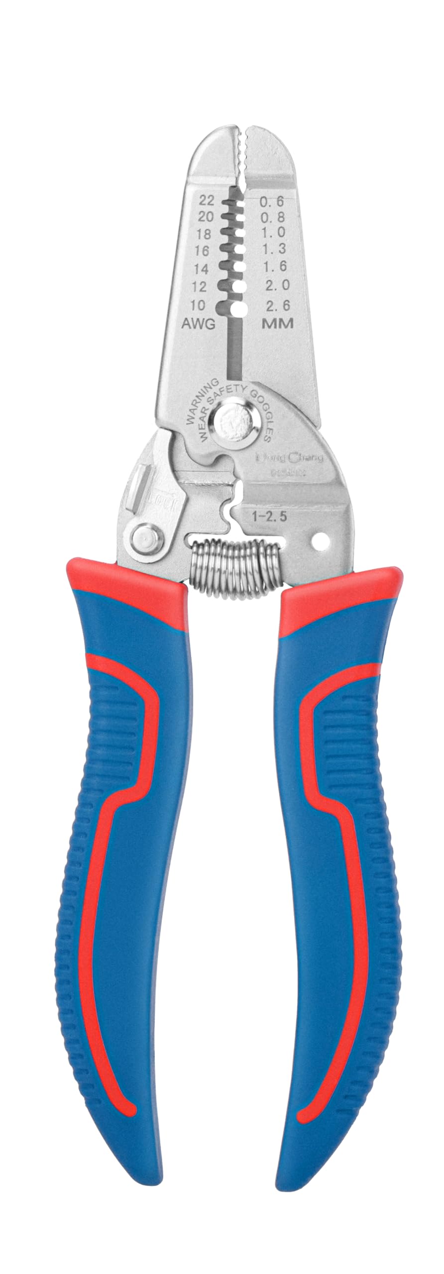
- •Wire strippers (adjustable preferred)
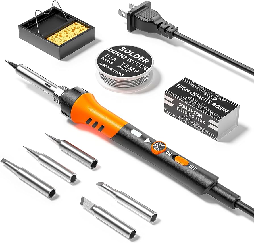
- •Soldering iron and solder (lead-free recommended)
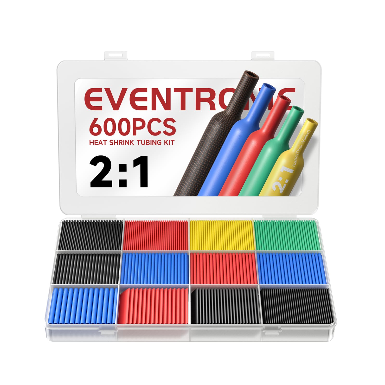
- •Heat shrink tubing (assorted sizes, 2–5 mm)
- •Heat gun or lighter (for shrinking tubing)
- •Multimeter (to test continuity after repair)
- •Electrical tape (optional, temporary insulation)
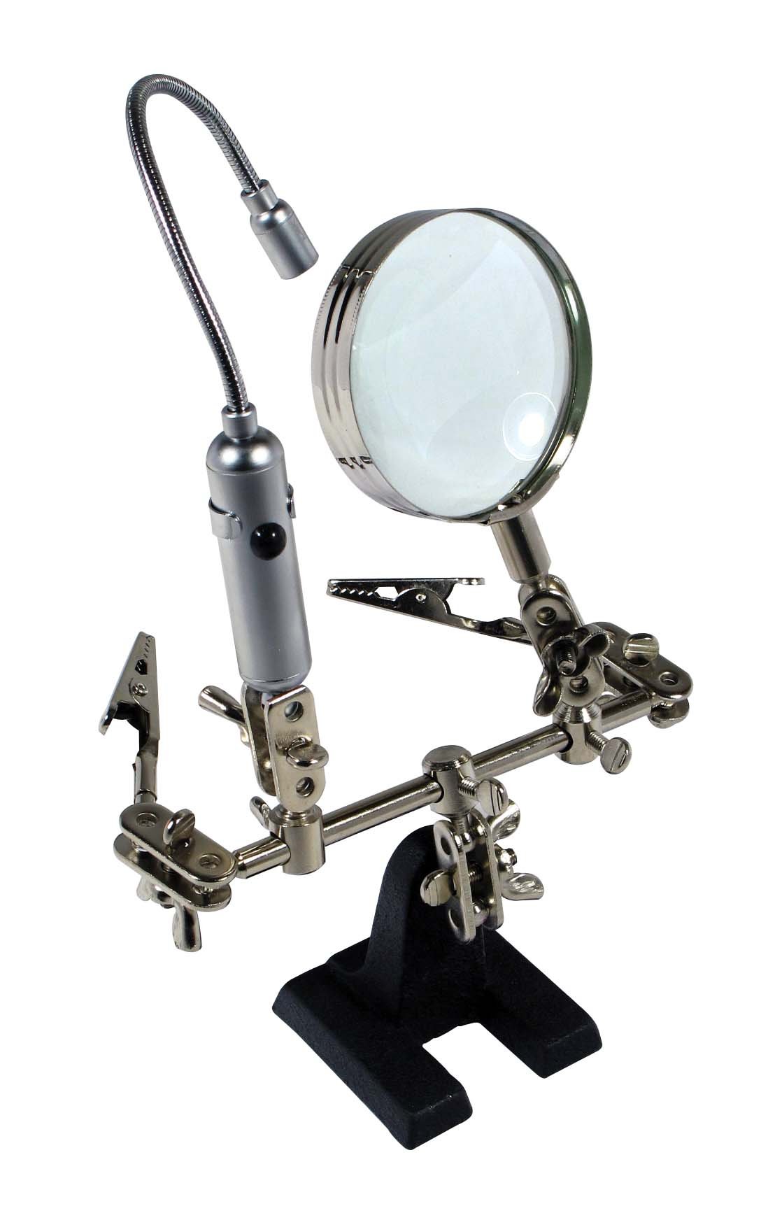
- •Helping hands or clamp (to hold wires while soldering)
- •Isopropyl alcohol and rag (to clean wires)
Estimated Time: 30–45 minutes
Difficulty: intermediate
▸Step-by-Step Instructions
Step 1: Assess the Damage and Prepare the Work Area
Inspect the adapter wire carefully. Look for cuts, exposed inner wires, or spots where the insulation is frayed. Determine whether the damage is close to the connector or in the middle of the cable. For safety, unplug the adapter from power before cutting. Clear a well-lit, ventilated workspace. Lay out all tools and materials. Put on safety glasses if you have them. If the damage is near the connector, you may need to cut off the connector and replace it; this guide focuses on repairing a break along the cable.
💡 Tips:
- •Take a photo of the wire orientation before cutting to remember which color goes where.
⚠️ Warnings:
- •Do not work on a live cable—ensure the adapter is unplugged from the wall. Even low-voltage wires can cause shocks if you cut through while plugged in.
Step 2: Cut Out the Damaged Section
Using wire cutters, cut the cable about 1–2 inches on each side of the damaged area. This ensures you remove all weakened insulation and any internal wire fatigue. Make a clean, perpendicular cut. You should now have two separate cable ends. If you cut near the connector, you'll have a short stub; you may need to work carefully. The goal is to have two fresh ends to splice together.
💡 Tips:
- •Leave a little extra length if you plan to reposition the connector or add stress relief later.
⚠️ Warnings:
- •Do not cut too close to the damage—internal wires may already be broken inside the insulation.
Step 3: Strip the Outer Insulation
Using wire strippers, remove about 1–1.5 inches of the outer jacket from both cable ends. Be careful not to nick the inner wires. Set the stripper to the appropriate gauge (most adapter cables are around 5–6 mm outer diameter). Once stripped, you'll see two or three inner wires (typically red, black, and sometimes white/green). Separate them gently with your fingers or a small screwdriver.
💡 Tips:
- •If you don't have wire strippers, carefully use a knife at a shallow angle to score the jacket, then pull it off with pliers. But strippers are safer.
⚠️ Warnings:
- •Avoid cutting into the inner wire insulation—a nick can cause a short or weak spot.
Step 4: Strip the Inner Wire Insulation
Strip about 3/8 inch (10 mm) of insulation from the end of each inner wire. Use a smaller setting on your wire strippers matching the wire gauge (typically 18–22 AWG). Twist the exposed copper strands tightly with your fingers to prevent fraying. Repeat for each wire on both cable ends. You should have 4–6 stripped ends total (depending on wire count).
💡 Tips:
- •If the strands are oxidized (dark), scrape them lightly with a knife or use fine sandpaper to expose shiny copper for better solder adhesion.
⚠️ Warnings:
- •Do not strip too much insulation—you can always trim later, but too much exposed wire increases risk of short circuits.
Step 5: Slide Heat Shrink Tubing onto Wires (Important: Do This Before Soldering!)
Cut two pieces of heat shrink tubing for each wire (one for each pair). The tubing should be long enough to cover the entire exposed section plus a bit of the original insulation. Slide one piece onto each wire of one cable end, pushing them several inches away from the splice area. This step is critical—if you forget, you'll have to desolder and start over. Also cut a larger piece of tubing to cover the entire outer jacket of the splice (optional but recommended for a clean finish).
💡 Tips:
- •Use tubing sized to fit snugly over the wire insulation. For inner wires, 2 mm tubing works; for outer jacket, 5–6 mm.
⚠️ Warnings:
- •Do not shrink the tubing yet—it must be positioned after soldering. Leave them loose.
Step 6: Tin the Wire Ends
Heat up your soldering iron to about 350°C (660°F). Touch the tip to the exposed copper of one wire, then feed a small amount of solder so it flows evenly into the strands. The wire should look shiny and silvered. Do this for all stripped ends. Tinning makes the wires easier to join and ensures a solid connection. Let each wire cool for a few seconds before moving on.
💡 Tips:
- •Apply flux to the wires if using lead-free solder—it helps the solder flow.
⚠️ Warnings:
- •Hold the soldering iron tip, not the shaft. Use a stand when not in use. Avoid breathing fumes—work in ventilated area.
Step 7: Splice the Wires (Connect Matching Colors)
Identify matching wires on both cable ends (e.g., red to red, black to black). If there is a white/green wire, match it as well. Overlap the tinned ends and twist them together with pliers or your fingers to form a secure mechanical joint. Then apply the soldering iron to the joint, adding a small amount of solder to fuse the wires completely. The joint should be shiny and smooth. Repeat for each pair. Allow joints to cool for about 30 seconds.
💡 Tips:
- •Use a 'helping hands' tool to hold both cable ends in alignment while you solder. This prevents movement.
⚠️ Warnings:
- •Do not overheat the joint—excessive heat can damage the wire insulation. If the insulation starts melting, you're too hot or too long.
Step 8: Insulate Each Splice with Heat Shrink
Slide the pre-placed heat shrink tubing over each soldered joint, positioning it so it covers the bare wire and overlaps the insulation on both sides. Use a heat gun or lighter to shrink the tubing. Move the heat source back and forth to avoid melting the insulation. The tubing will shrink tightly around the joint. Repeat for all inner wire splices. Ensure the tubing covers all exposed metal.
💡 Tips:
- •If using a lighter, use the blue flame tip and keep it moving. Hold the wire away from your face.
⚠️ Warnings:
- •Do not hold the heat gun too close—the tubing can burn or become brittle. Test with a small piece if unsure.
Step 9: Reassemble the Outer Jacket (Optional but Recommended)
If you cut a larger piece of heat shrink tubing earlier, slide it over the entire repaired area. Position it so it covers the outer jacket on both sides of the splice. Shrink it with heat. This restores mechanical strength and provides strain relief. If you don't have large tubing, wrap the area with electrical tape in layers, overlapping each wrap by 50%. Ensure no bare wire or inner splices are exposed.
💡 Tips:
- •Use adhesive-lined heat shrink for extra durability. It creates a waterproof seal.
⚠️ Warnings:
- •Do not apply tape too tightly; it can deform the inner wires over time.
Step 10: Test the Repair with a Multimeter
Set your multimeter to continuity (or resistance mode). Touch one probe to the barrel of the adapter connector (positive tip) and the other probe to the corresponding wire at the cut end. You should hear a beep or see near-zero resistance. Test all wires similarly. Also check for shorts between wires (no continuity). If everything passes, plug in the adapter and test it with your device. Check that the device charges/works normally.
💡 Tips:
- •If you don't have a multimeter, plug the adapter into a low-value resistor (e.g., a small fan) to test. But a multimeter is strongly recommended for safety.
⚠️ Warnings:
- •Do not use the adapter if you detect shorts or intermittent connections—it can damage your device.
Step 11: Add Strain Relief (Optional for Longevity)
To prevent future breaks, reinforce the cable near the connector or any bend point. You can use a spring from a pen or a dedicated cable protector. Alternatively, wrap the end with heat shrink tubing that is slightly larger, creating a flexible 'boot'. Some people use Sugru moldable glue to create a custom strain relief. This step is crucial if the original break was near the connector.
💡 Tips:
- •A simple method: slide a piece of fuel line tubing over the cable and connector, then heat shrink it at both ends.
⚠️ Warnings:
- •Do not add excessive bulk that prevents the connector from fitting into tight spaces.
▸Pro Tips
- •Always use lead-free solder for electronics to comply with safety standards and avoid toxic fumes.
- •If the wire is very thin, use a lower temperature iron (300°C) to avoid melting the thin insulation.
- •Tinning both wires before splicing reduces the chance of cold solder joints.
- •Use a 'third hand' tool with a magnifying glass for precision work on small wires.
- •Mark the wires with tape if you're colorblind—some adapters use non-standard colors.
- •Practice on scrap wires before attempting the actual repair if you're new to soldering.
- •For a quick temporary fix, twist wires and use electrical tape, but it won't last long.
▸Common Mistakes to Avoid
- •Forgetting to slide heat shrink tubing before soldering leads to having to desolder and start over.
- •Using too much solder can create blobs that short to adjacent wires or crack when flexed.
- •Cutting the cable too close to the damage—internal wires may be already weak or broken inside the insulation.
- •Not stripping enough insulation, resulting in poor solder coverage and weak mechanical joint.
- •Rushing the heat shrink step and melting the wire insulation instead of the tubing.
▸Troubleshooting
Problem: Multimeter shows no continuity after repair.
Solution: Check each solder joint for cold solder or break. Reheat and add fresh solder if needed. Also verify that wires are properly matched (red to red, black to black).
Problem: Device doesn't charge or work after repair.
Solution: Test the adapter with a multimeter on voltage mode to ensure output is correct. If voltage is low, there may be a short or wrong wire connection. Recheck splices.
Problem: Repair works but breaks again after a few uses.
Solution: Add proper strain relief as described in step 11. Also consider that the conductor inside may be damaged further up; cut back and re-splice a longer section.
Problem: Solder won't stick to the wire.
Solution: The wire might be oxidized or dirty. Clean with sandpaper or isopropyl alcohol. Apply flux, then tin the wire.
Problem: Heat shrink tubing burns or melts.
Solution: Your heat source is too hot or too close. Keep the heat gun at 2-3 inches distance, move constantly. For a lighter, use the blue inner flame carefully.
Soldering Iron Kit with Temperature Control
A reliable adjustable soldering iron is essential for clean, safe joints. Temperature control prevents overheating thin wires.
Best for: For the soldering step and tinning wires
Price Range: $30-$60
Wire Strippers with Multiple Gauges
Precision wire strippers allow you to strip the outer jacket and inner wires without nicking the conductor, reducing chance of breakage.
Best for: For stripping insulation at steps 3 and 4
Price Range: $15-$25
Heat Shrink Tubing Assortment Kit
An assortment of sizes ensures you have the right fit for both inner wires and outer jacket. Adhesive-lined type adds durability.
Best for: For insulating splices and reinforcing outer jacket
Price Range: $10-$20
Helping Hands with Magnifying Glass
Holds wires steady while you solder, freeing both hands. Magnification helps see small connections clearly.
Best for: For holding wires during soldering (step 7)
Price Range: $10-$18
Digital Multimeter
Essential for testing continuity and voltage after repair. Verifies that the adapter is safe to use before plugging into device.
Best for: For testing repair (step 10) and troubleshooting
Price Range: $15-$30