Got a drawer full of outdated AC adapters with barrel plugs gathering dust? In a world dominated by USB-C devices like smartphones, laptops, and Raspberry Pi projects, those legacy adapters are useless without modification. Converting them to USB-C output revives them, saving money and reducing e-waste.
This advanced guide teaches you to safely hack a 5V DC adapter by replacing its output connector with a USB-C female port. You'll learn electronics basics like polarity verification, soldering, and USB-C pinout compliance for basic 5V/3A charging (no PD negotiation). Expect 45-60 minutes of hands-on work if you're comfortable with a soldering iron.
Warning: This mod involves high-voltage AC components and DC output risks. Mains electricity can kill—work only if experienced. Test thoroughly to avoid damaging devices.
▸What You'll Need
- •5V DC AC-DC adapter (2-3A output, barrel jack or similar; verify voltage with multimeter)
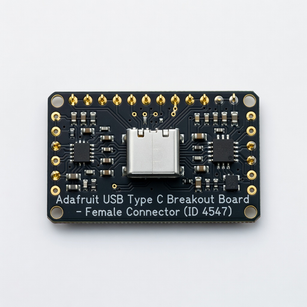
- •USB-C female breakout board or 16-pin socket (with built-in 5.1kΩ CC pull-down resistors for 5V charging)
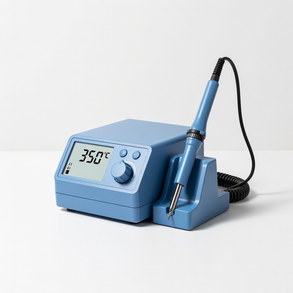
- •Soldering iron (60-80W with fine tip) and lead-free solder
- •Wire strippers, flush cutters, and helping hands clamp
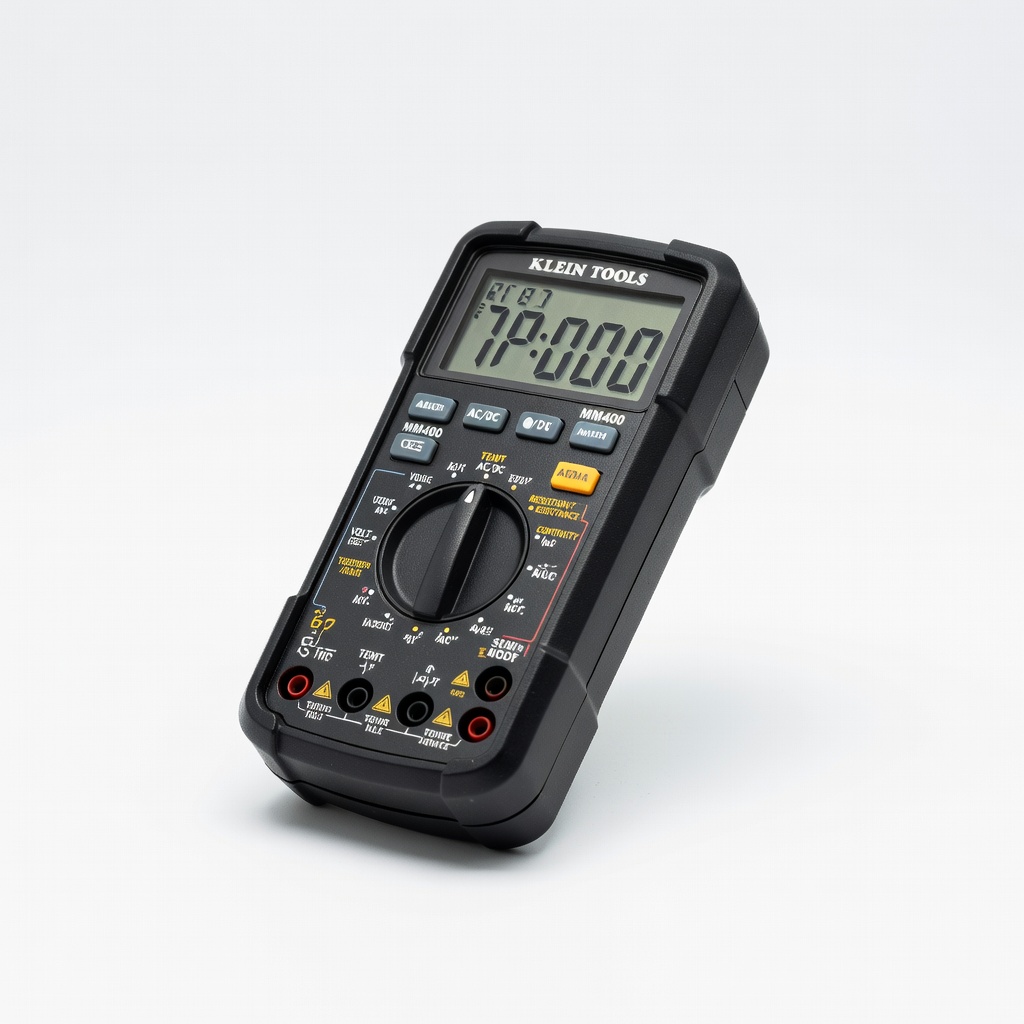
- •Digital multimeter for voltage/polarity checks
- •Heat shrink tubing (3-5mm diameter) or electrical tape
- •Optional: Desoldering wick/pump, hot glue gun for strain relief
Estimated Time: 45-60 minutes
Difficulty: advanced
▸Step-by-Step Instructions
Step 1: Verify Adapter Specs and Safety
Unplug the adapter from mains power. Use your multimeter in DC voltage mode to confirm output: plug in (stand clear), probe center (positive) and sleeve (ground) of barrel jack—expect ~5V. Measure current capability indirectly by shorting output briefly (amps mode) or check label.
Why? USB-C devices expect 5V nominal; mismatch fries them. Discharge capacitors by holding plug shorted for 1 minute post-unplug.
Success: Confirmed 5.0-5.2V DC, polarity (+ center standard).
💡 Tips:
- •Label wires early with red (+) / black (-).
⚠️ Warnings:
- •Never probe AC side live without isolation transformer.
Step 2: Disassemble the Adapter
Most adapters are potted or sealed—crack open with a flathead screwdriver or Dremel cutoff wheel along seams. Avoid damaging transformer or PCB. If wires exit directly, skip to cutting.
Locate output wires (usually red/black twisted pair from rectifier). Note polarity via PCB traces (thicker to +).
Success: Exposed wires and PCB intact.
💡 Tips:
- •Wear safety glasses; epoxy shards fly.
Step 3: Remove Old Output Connector
Cut output cable 6 inches from PCB, or desolder if soldered. Strip 1/4 inch insulation from ends. Use multimeter continuity mode to confirm + and - to PCB pads.
Why? Clean splice for reliable connection. Desoldering preserves PCB if mod fails.
Success: Bare wire ends ready, polarity confirmed.
⚠️ Warnings:
- •Inverse polarity on USB-C outputs -5V—dead devices.
Step 4: Prepare USB-C Breakout Board
Mount USB-C female socket on breakout if needed. Solder short jumper wires to VBUS (5V+, pins A4/A9/B4/B9), GND (A1/A12/B1/B12), and CC1/CC2 (A5/B5 with 5.1kΩ to GND for 5V advertisement).
Basic boards have resistors pre-installed. Tin pads with solder.
Success: Board ready with tinned VBUS/GND pads.
💡 Tips:
- •Use breakout like Adafruit #4547 for foolproof CC config.
Step 5: Solder Wires to USB-C Board
Clamp in helping hands. Solder adapter + wire to VBUS pad, - to GND. Add 22AWG wire extensions if needed. Flow solder joints shiny, no bridges.
Why? Solid mechanical/electrical bond handles 3A draw.
Success: Secure solders, continuity test beeps.
⚠️ Warnings:
- •Cold joints fail under load—reheat 3-5 sec.
Step 6: Insulate and Strain Relieve
Slide heat shrink over wires pre-solder, shrink with heat gun. Hot glue cable to case for flex relief. Reassemble enclosure loosely.
Success: No shorts, pulls withstand 10lbs force.
Step 7: Test the Conversion
Multimeter: 5V across VBUS/GND on USB-C pins. Plug USB-C cable + dummy load (phone/5V bulb)—charges? Monitor temp <60°C after 10min.
Success: Stable 5V/2A+ output, device charges happily.
💡 Tips:
- •Use USB power meter for precise amps/volts.
▸Pro Tips
- •Choose adapters >2A rated for fast charging.
- •Add inline fuse (5A) for overcurrent protection.
- •For PD (20V), add chip like IP2721—beyond basic mod.
- •Epoxy pot internals post-mod for safety.
- •Batch mod multiple adapters for projects.
- •Verify CC resistance: 5.1kΩ ensures 5V profile.
- •Use flux for clean USB-C pin solders.
▸Common Mistakes to Avoid
- •Wrong polarity: Reverses VBUS/GND—fries devices. Always multimeter-check.
- •Skipping CC resistors: Devices detect 0V profile, refuse charge.
- •Undersized wires/solders: Melts at 2A+. Use 20-22AWG.
- •Poor insulation: Shorts cause fires. Double up heat shrink.
- •No temp testing: Overheating indicates bad joints.
▸Troubleshooting
Problem: No output voltage
Solution: Check solder bridges/shorts; verify polarity; test adapter original.
Problem: Device won't charge
Solution: Confirm CC pull-downs; try different cable/device.
Problem: Overheats during use
Solution: Resolder cold joints; ensure >3A rating; add heatsink to regulator.
Problem: Sparking/shock
Solution: Stop! Exposed AC—rewire DC only, seek pro if unsure.
Adafruit USB Type C Breakout Board - Female Connector (ID 4547)
Pre-configured CC resistors for 5V output, perfect for safe USB-C source mod.
Best for: Core component for soldering adapter wires—handles up to 3A.
Price Range: $4.95
Hakko FX-888DX Digital Soldering Station
Precise temp control (50-480°C) for tiny USB-C pins without overheating.
Best for: Essential for pro joints on breakout boards.
Price Range: $99.99
Klein Tools MM400 Digital Multimeter
Accurate DCV/continuity for polarity and output verification.
Best for: Safety checks before/after mod.
Price Range: $29.99
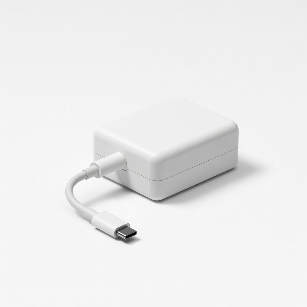
Official Raspberry Pi 5V 5A USB-C Power Supply
High-quality base adapter if yours is junk—mod its internals easily.
Best for: Upgrade source for PD-capable mods.
Price Range: $12.99
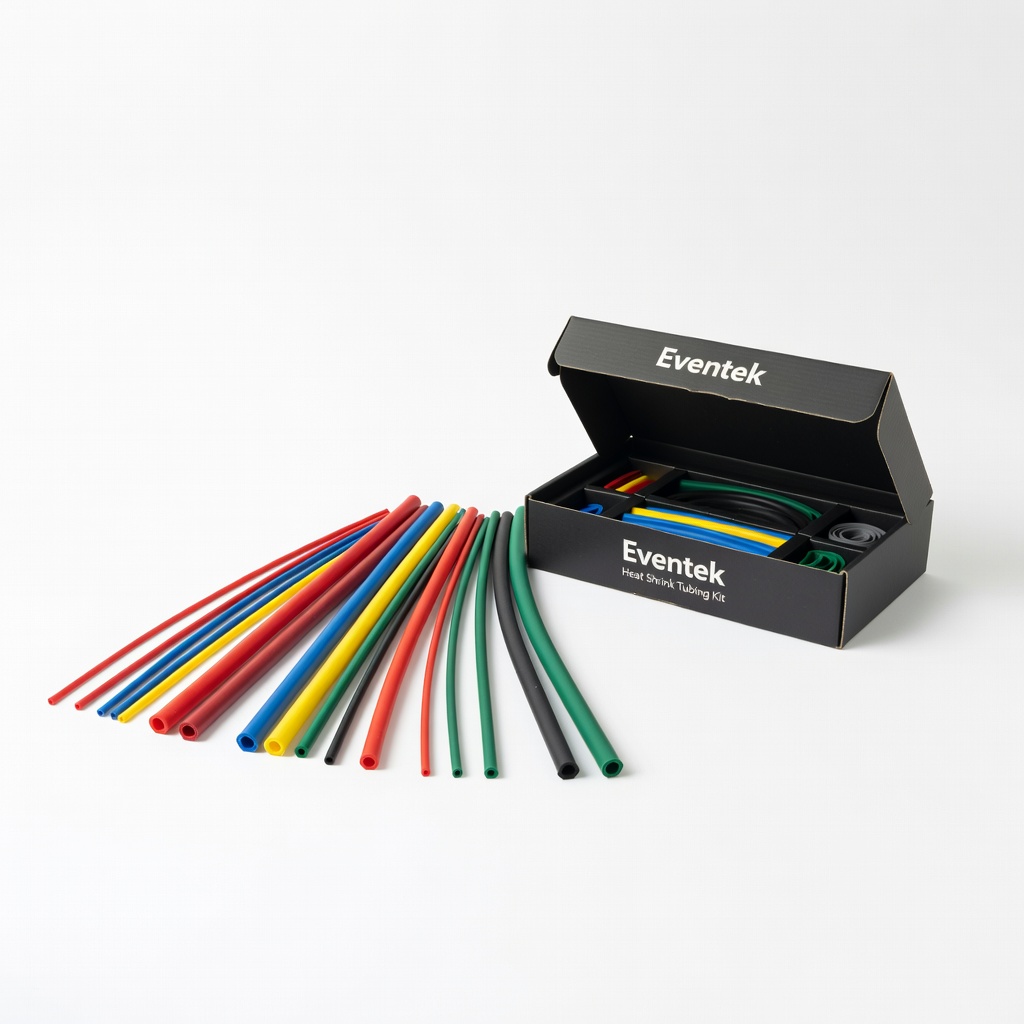
Eventek Heat Shrink Tubing Kit
Assorted sizes for bulletproof insulation on high-current wires.
Best for: Post-solder protection.
Price Range: $9.99