
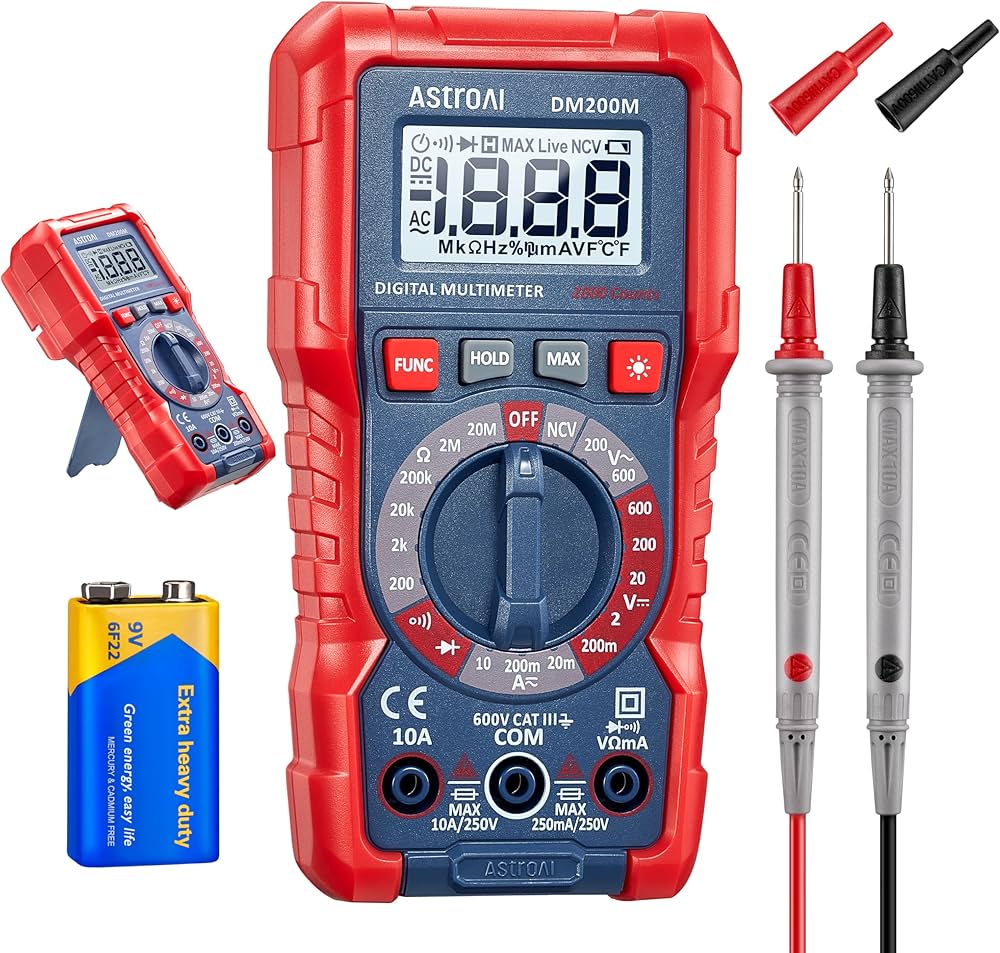
AstroAI Digital Multimeter
Measure output at every step; auto-ranging for beginners.
$12.99
AstroAI Digital Multimeter Accurate DC/AC voltage testing essential for safe verification.
Get the App
Better experience on mobile
Repurpose old phone chargers into a reliable, compact 5V power supply for Arduino, Raspberry Pi, or DIY projects in under an hour.
Tired of buying expensive power supplies for your electronics projects while old phone adapters gather dust? Building a custom 5V power supply from salvaged adapters saves money, reduces e-waste, and gives you a tailored solution for breadboards, sensors, or LED strips. It's a smart hack for hobbyists who want stable power without the hassle of new purchases.
In this guide, you'll learn to safely disassemble adapters, test their output, and assemble a clean, modular 5V supply with screw terminals or barrel jacks. Perfect for intermediate makers familiar with basic soldering and multimeters. The process takes 45-60 minutes and results in a reusable power source rated for 1-2A, depending on your adapters.
Expect hands-on work with tools like a soldering iron—safety first, as adapters have high-voltage internals. By the end, you'll have a professional-looking supply ready for your next project.
Estimated Time: 45-60 minutes Difficulty: intermediate
Start by collecting 2-3 old 5V USB adapters from phones, tablets, or chargers. Check labels for 'Output: 5V 1A' or higher—avoid anything under 1A or non-5V. Test each with a USB multimeter dongle if available, or plug into a device to confirm they work.
Why? Reliable adapters ensure stable power; mismatched ones can fail under load. Success looks like 2-3 working units with clean USB outputs.
💡 Tips:
⚠️ Warnings:
Unplug the adapter. Use a screwdriver to pry open the plastic case—most snap apart or have clips/screws. Gently remove the PCB, exposing the transformer, rectifier, and output wires.
Critical safety: Discharge electrolytic capacitors by shorting leads with an insulated screwdriver (wear gloves). The primary side (AC input) holds lethal voltage—do not touch.
Expect a small PCB with red/black output wires from the USB port or regulator.
💡 Tips:
⚠️ Warnings:
Set multimeter to DC volts (20V range). Connect probes to output pads/wires (red to positive, black to ground). Plug in and measure—should read 4.8-5.2V steady.
Reverse probes to confirm polarity (negative reading means swapped). Test under light load (e.g., 100Ω resistor) for voltage sag.
Success: Stable 5V, no ripple >0.1V on AC setting.
💡 Tips:
⚠️ Warnings:
Heat soldering iron to 350°C. Desolder USB output wires or pads carefully—tin the pads first for clean joints. Cut wires 6-8 inches long, strip 1/4 inch insulation.
Why extend? Allows custom connectors far from the PCB. Solder on thicker 22AWG wire if original is thin for higher current.
💡 Tips:
⚠️ Warnings:
Solder wires to a screw terminal block (for breadboard) or 5.5x2.1mm barrel jack (common for modules). Red to +, black to -. Tin joints for strength.
This makes it modular—plug into projects easily. Test continuity from PCB to connector.
💡 Tips:
⚠️ Warnings:
Slide heat shrink tubing over wires/joints before soldering, then shrink with a heat gun or lighter. Wrap PCB exposed points with electrical tape.
Prevents shorts—essential for safety. Your assembly should now be fully insulated except input plug and output.
💡 Tips:
⚠️ Warnings:
Reassemble loosely if desired. Power on, measure output at connector: 5V steady, no heat buildup after 5 mins.
Load test with a 5Ω/10W resistor (1A draw)—voltage drop <0.2V is good. Success: Reliable power for your LED or Arduino.
💡 Tips:
⚠️ Warnings:
Drill holes in a small plastic box for input plug, output jack, and vents. Secure PCB with standoffs or hot glue. Label voltage/polarity.
Professional finish protects and organizes. Your custom 5V supply is now project-ready!
💡 Tips:
⚠️ Warnings:
Problem: No output voltage
Solution: Check input AC fuse/continuity; replace blown fuse or bad bridge rectifier.
Problem: Voltage drops under load
Solution: Upgrade to higher-amp adapter or parallel units; check wire gauge.
Problem: Overheating
Solution: Improve airflow; desolder and reapply thermal paste if on regulator.
Problem: Intermittent power
Solution: Resolder loose joints; ensure clean PCB contacts.
Accurate DC/AC voltage testing essential for safe verification.
Best for: Measure output at every step; auto-ranging for beginners.
Price Range: $12.99
Reliable temperature control prevents PCB damage during desoldering.
Best for: Desolder USB ports and attach connectors cleanly.
Price Range: $13.99
Assorted sizes for perfect insulation fits.
Best for: Protect all joints from shorts in final assembly.
Price Range: $9.99
Standard connector for most modules; solder-ready.
Best for: Custom output for breadboards or enclosures.
Price Range: $6.99 (pack of 10)
Compact housing protects internals affordably.
Best for: Final mounting for portable, safe supply.
Price Range: $9.99
Measure output at every step; auto-ranging for beginners.
AstroAI Digital Multimeter Accurate DC/AC voltage testing essential for safe verification.
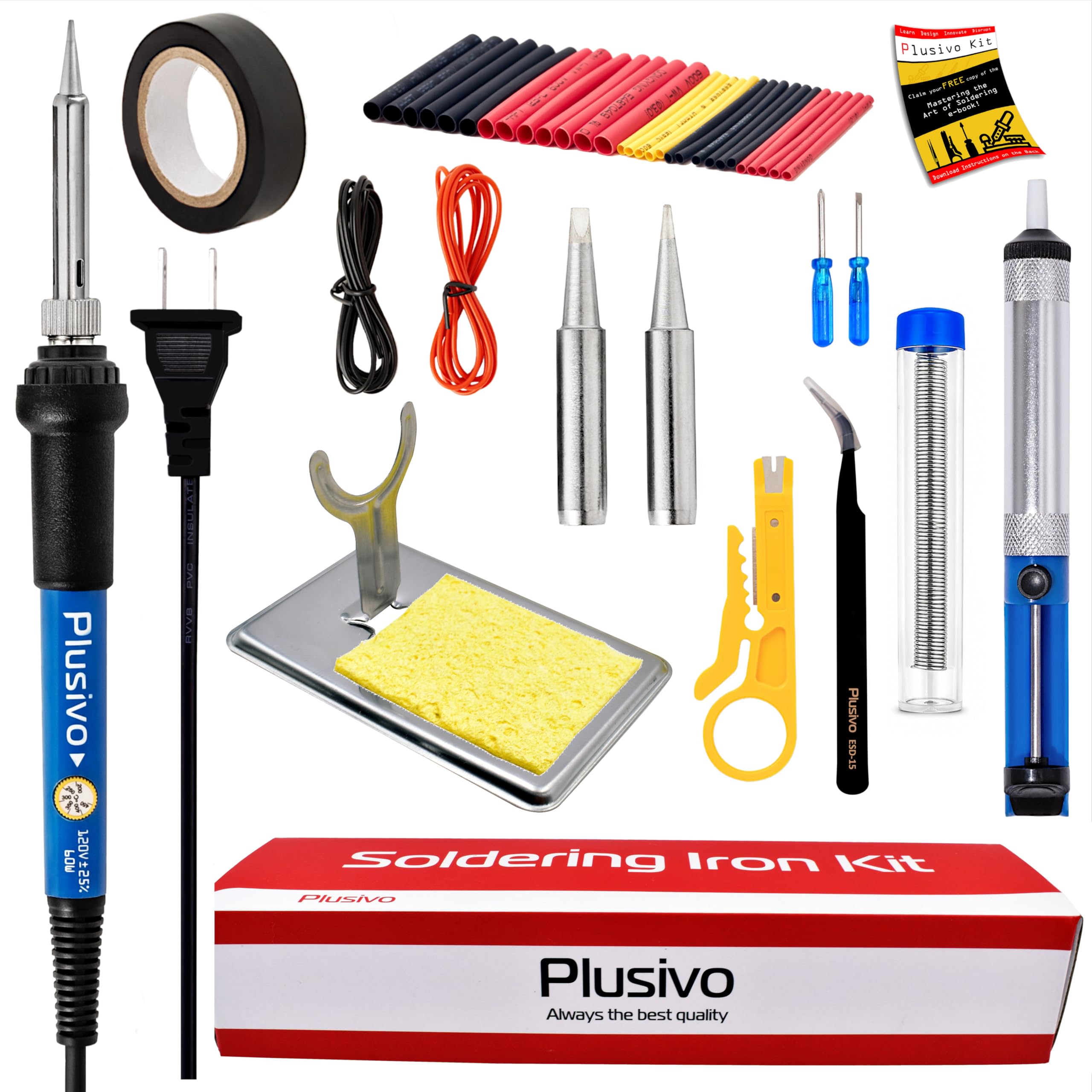
Desolder USB ports and attach connectors cleanly.
Soldering Iron Kit, 60W Adjustable Reliable temperature control prevents PCB damage during desoldering.
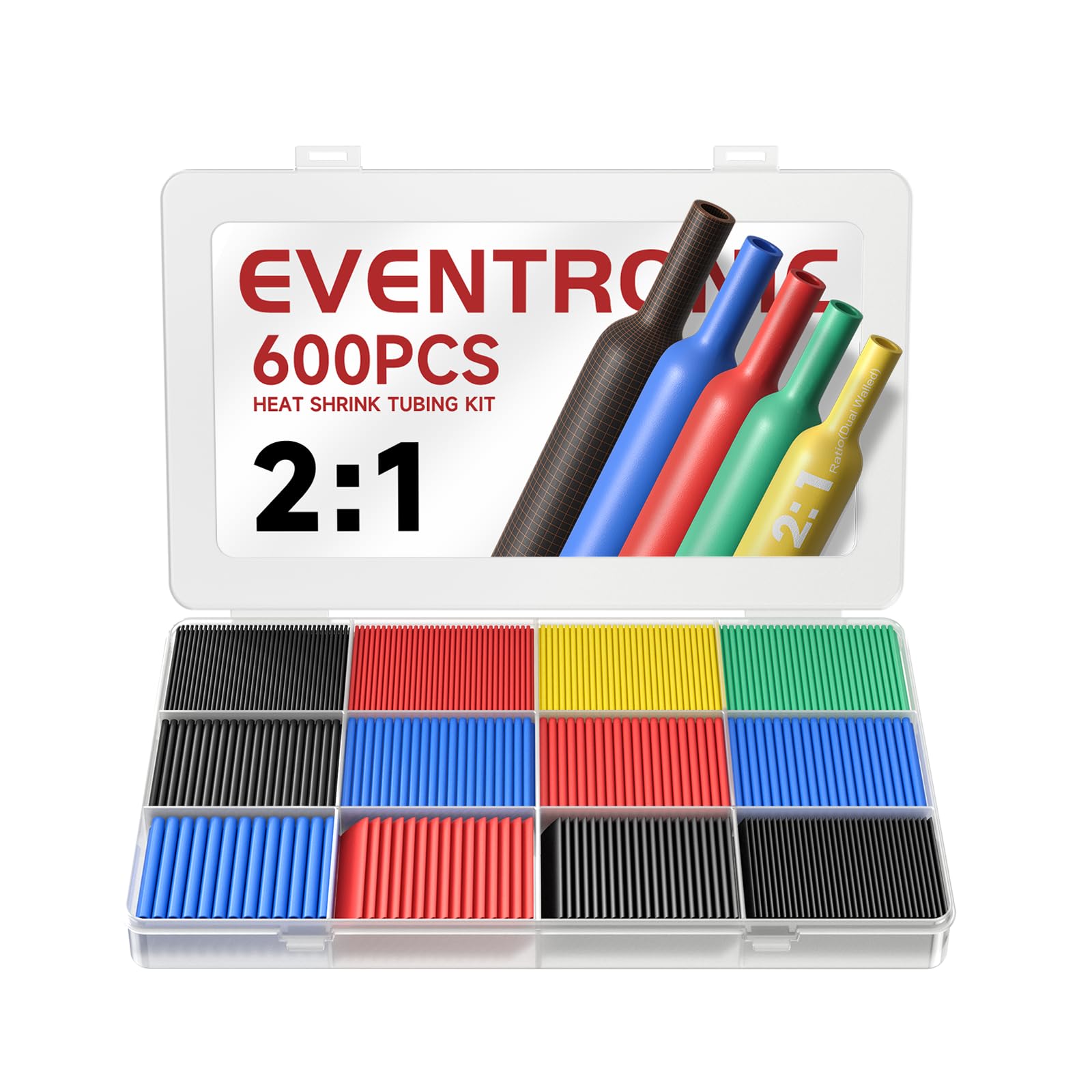
Protect all joints from shorts in final assembly.
Eventronic Heat Shrink Tubing Kit Assorted sizes for perfect insulation fits.
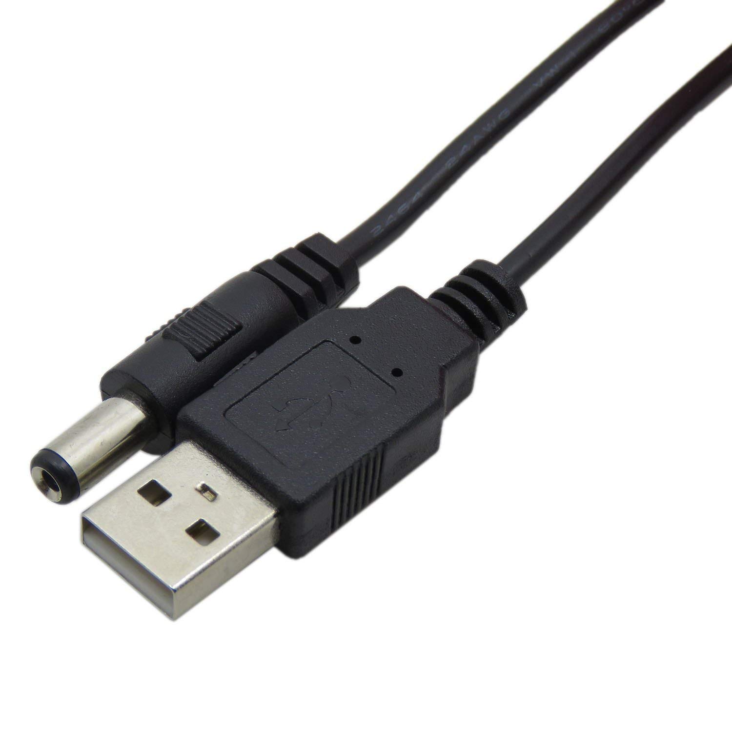
Custom output for breadboards or enclosures.
HiLetgo DC Power Jack 5.5x2.1mm Standard connector for most modules; solder-ready.
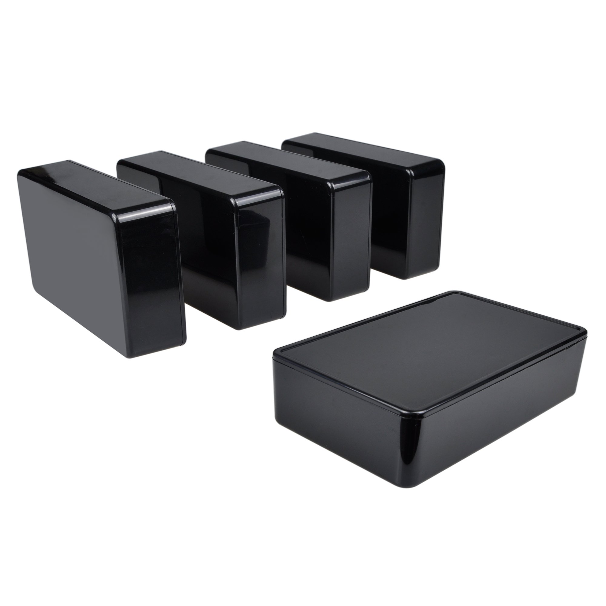
Final mounting for portable, safe supply.
ABS Plastic Project Enclosure Compact housing protects internals affordably.